Step 1: Capacity Selection
Selecting the correct capacity is the most critical step in load cell selection. The rated capacity should be chosen so that your maximum expected load falls between 50% and 80% of the load cell's rated capacity. This ensures you operate within the sensor's optimal accuracy range while maintaining a safe overload margin.
Key considerations: • Never size at 100% of your expected maximum load. Always leave headroom for dynamic loads, shock, and safety. • Avoid oversizing: Operating below 10% of rated capacity results in poor signal-to-noise ratio and unreliable readings. • Account for dead loads: If your fixture or tooling applies a constant load (tare), include it in capacity calculations.
Example: If your testing machine applies a maximum force of 500 kN, select a load cell rated between 600 kN to 1000 kN. A 1000 kN rated cell gives you a 2:1 safety margin, which is standard for most industrial applications.
At JRAGRAU, we manufacture load cells from 300 grams to 100 tons, covering applications from micro-force lab testing to heavy industrial weighing.
Step 2: Understanding Accuracy Parameters
Load cell accuracy is defined by several interrelated specifications. Understanding these parameters helps you match the sensor to your measurement requirements.
| Parameter | Definition | Typical Value |
|---|---|---|
| Non-linearity | Maximum deviation from a straight-line calibration curve | ±0.02% to ±0.1% FSO |
| Hysteresis | Difference in output between increasing and decreasing loads at the same point | ±0.02% to ±0.05% FSO |
| Repeatability | Maximum difference between outputs for repeated identical loads | ±0.01% to ±0.03% FSO |
| Creep | Output change over time under constant load | ±0.02% to ±0.05% FSO over 30 min |
| Zero Balance | Output signal when no load is applied | ±1% to ±2% FSO |
Combined Error is the total accuracy specification that includes non-linearity, hysteresis, and repeatability. For most industrial applications, a combined error of ±0.05% FSO is sufficient. For calibration-grade work, you need ±0.02% FSO or better.
For a deeper understanding, read our guide on Understanding Load Cell Accuracy.
Step 3: Choosing the Right Load Cell Type
Different load cell types are optimized for different mounting configurations and loading directions:
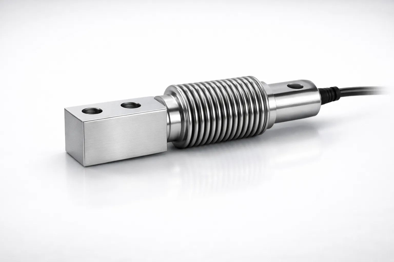
Bending Beam Load Cells — Best for platform scales, conveyor weighing, and single-point applications. Mount on a flat surface with load applied to the free end. Capacities: 300g to 500 kg.
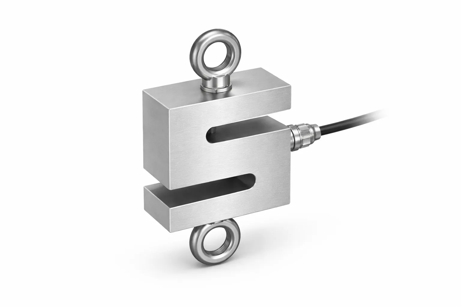
S-Type Load Cells — Versatile sensors for both tension and compression. Ideal for crane scales, hopper weighing, and material testing machines. Require rod-end bearings for proper alignment. Capacities: 2 kg to 10 tons.
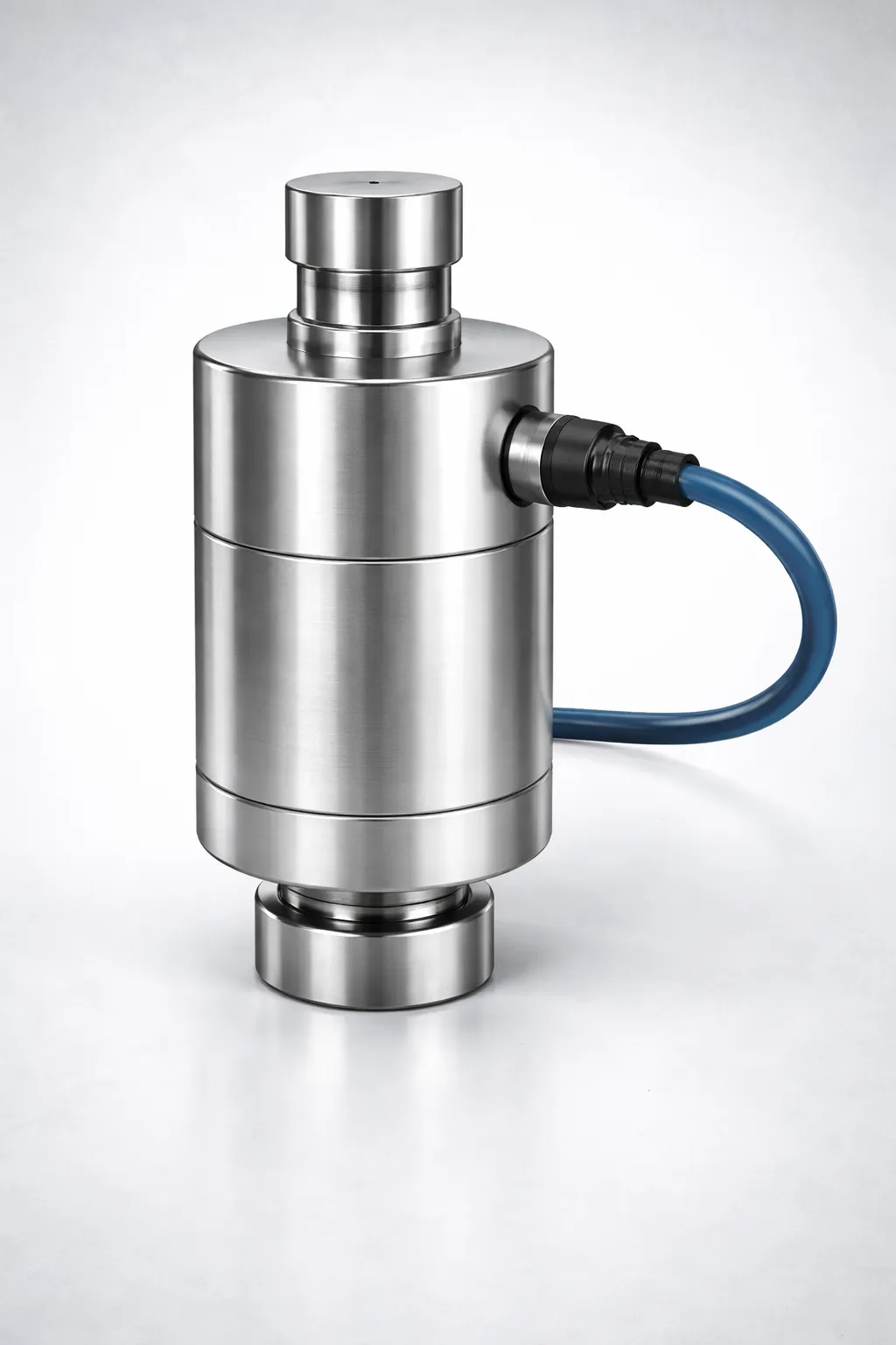
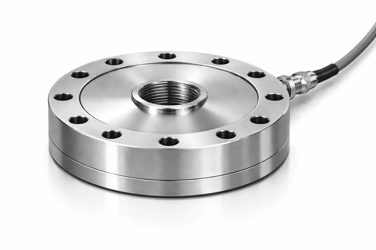
Compression Load Cells — Designed for heavy-capacity applications where the load is applied directly from above. Used in silo weighing, concrete testing, and hydraulic press monitoring. Capacities: 1 kN to 2000 kN.
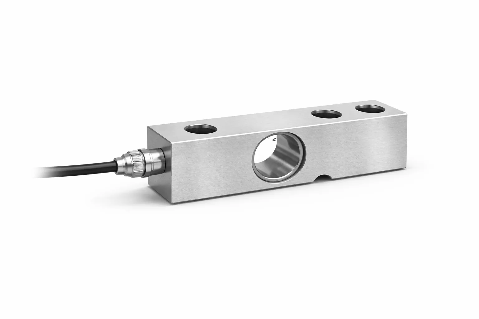
Single Ended Shear Beam — The workhorse of industrial weighing. Used in floor scales, pallet scales, and tank weighing. Resistant to side loads and easy to mount. Capacities: 100 kg to 5 tons.
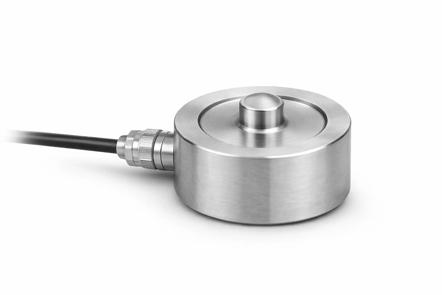
Low Profile Load Cells — For applications with height restrictions. Provide high accuracy in a compact form factor.
Button / Miniature Load Cells — Ultra-compact compression sensors for OEM integration, medical devices, and space-constrained applications. Capacities from 50 kg to 50 tons.
Need Help Choosing the Right Solution?
Our engineering team has 20+ years of experience in force, torque, and pressure measurement. Get expert guidance for your specific application.
Step 4: Environmental Factors
The operating environment directly impacts which load cell construction and protection class you need:
IP Protection Rating: • IP65 — Dust-tight, protected against water jets. Suitable for most indoor industrial environments. • IP67 — Dust-tight, protected against temporary immersion. Required for washdown environments, food processing, and outdoor applications. • IP68 — Dust-tight, protected against continuous submersion. Required for underwater or chemical processing.
Temperature: • Standard load cells operate from -10°C to +50°C. For extreme environments (furnaces, cold storage), specify compensated temperature ranges. • Temperature coefficient of zero and span should be considered for applications with wide temperature swings.
Corrosion: • Alloy steel is standard and cost-effective for clean, dry environments. • Stainless steel is recommended for food, pharmaceutical, chemical, and outdoor applications. • Hermetically sealed sensors are required where moisture ingress could compromise strain gauge integrity.
Vibration & Shock: • For environments with vibration (near motors, compressors), choose load cells with higher overload ratings (200-300% of capacity) and consider mechanical vibration isolators.
Step 5: Mounting Considerations
Proper mounting is essential for accurate measurement. Common mounting errors can introduce significant measurement errors:
Critical rules: 1. Load must be applied along the primary axis. Off-axis loading introduces bending moments and side forces that corrupt the measurement. 2. Mounting surfaces must be flat and rigid. A flexing base plate will absorb load and give low readings. 3. Use proper hardware. Mounting bolts should be torqued to manufacturer specifications. Over-tightening can pre-stress the sensing element. 4. Cable routing matters. Don't route cables near high-power lines. Use shielded cables in electrically noisy environments.
Alignment aids: • Use spherical washers or self-aligning mounts for compression load cells to compensate for surface irregularities. • Rod-end bearings are essential for S-Type load cells to prevent side loading. • Spacer blocks should be used under bending beam sensors to allow free deflection.
At JRAGRAU, we provide complete mounting hardware and detailed installation drawings with every load cell we manufacture. Our engineering team offers free installation guidance for complex applications.