What is Calibration?
Calibration is the process of comparing a measurement instrument's output against a known reference standard, determining the deviation, and documenting the results.
In force and torque measurement, calibration answers one question: "How far off is this sensor from the true value?"
Calibration does NOT mean adjustment. Many people confuse the two: • Calibration = Measure and document the difference between the sensor reading and the true value • Adjustment = Physically changing the sensor's response to reduce that difference
A properly calibrated sensor with known errors can produce accurate results through mathematical correction. An adjusted but uncalibrated sensor gives false confidence.
The output of calibration is a calibration certificate that documents: • As-found readings (before any adjustment) • As-left readings (after adjustment, if performed) • Measurement uncertainty • Traceability to national/international standards • Environmental conditions during calibration
Why Calibration Matters for Industry
Calibration is not optional — it's a fundamental requirement for reliable measurement. Here's why:
Quality compliance: ISO 9001, IATF 16949, and AS9100 all require documented evidence that measuring instruments are calibrated at defined intervals. An uncalibrated load cell on a production line can invalidate every test result it produces.
Safety: In structural testing, crane load monitoring, and automotive component testing, an out-of-calibration sensor can pass a defective part or overload a structure.
Cost savings: An out-of-tolerance force sensor on a material testing machine can cause: • False rejections of good material (increased scrap cost) • False acceptance of bad material (warranty claims, recalls) • Both are expensive. Regular calibration prevents both.
Legal requirements: Many industries have regulatory mandates for calibration: • IS 14513 for weighing instruments in India • OIML R 60 for international load cell verification • ISO 7500 for testing machine verification
The Calibration Process
A proper force or torque calibration follows a systematic procedure:
Step 1: Pre-calibration checks • Visual inspection for physical damage, corrosion, cable integrity • Zero balance check • Insulation resistance test (>5000 MΩ recommended)
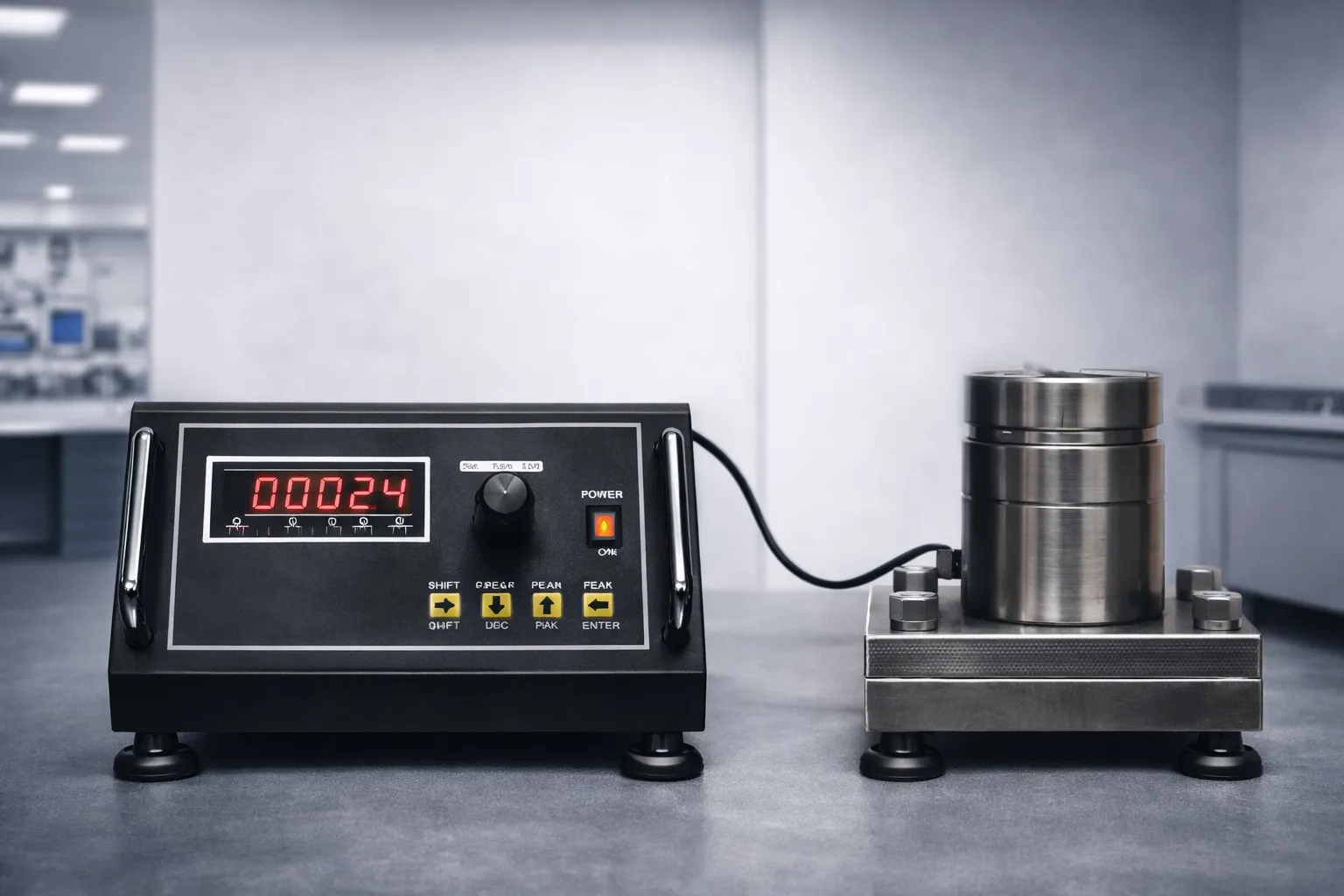
Step 2: Reference standard setup • The reference standard must be at least 4x more accurate than the device under test (4:1 Test Uncertainty Ratio, or TUR) • For a ±0.05% load cell, the reference standard must be ±0.0125% or better • Reference weights must be traceable to national standards (NPL India or equivalent)
Step 3: Loading sequence • Apply loads at minimum 5 points across the range (typically 0%, 20%, 40%, 60%, 80%, 100%) • Record readings on both increasing (loading) and decreasing (unloading) cycles • Take at least 3 runs to assess repeatability
Step 4: Data analysis • Calculate non-linearity, hysteresis, repeatability from the recorded data • Determine combined error • Calculate measurement uncertainty per GUM (Guide to the Expression of Uncertainty in Measurement)
Step 5: Certificate generation • Document all as-found and as-left data • State pass/fail against specified tolerance • Record environmental conditions (temperature, humidity) • Reference the calibration standard used and its own calibration status
Need Calibration Support?
JRAGRAU manufactures calibration systems and provides traceable calibration services for force and torque instruments.
Recommended Calibration Intervals
There is no universal "correct" calibration interval — it depends on your application, risk tolerance, and regulatory requirements. Here are industry-accepted guidelines:
| Application | Recommended Interval | Rationale |
|---|---|---|
| Calibration laboratory reference | 6 months | Highest accuracy required |
| Material testing machines (QC) | 12 months | IS 1828 / ISO 7500 compliance |
| Production weighing | 12 months | ISO 9001 requirement |
| Crane scales & safety-critical | 6-12 months | Safety risk |
| Research & development | 12-24 months | Lower risk, controlled use |
Factors that shorten intervals: • High-cycle usage (thousands of loading cycles per day) • Harsh environment (extreme temperature, vibration, chemical exposure) • History of drift or out-of-tolerance findings • Regulatory mandates
Factors that allow longer intervals: • Light duty usage • Controlled laboratory environment • Consistent in-tolerance history over 3+ calibration cycles • Regular intermediate checks with a check weight
Best practice: Use a daily or weekly check weight at approximately 50-80% of capacity to monitor for drift between formal calibrations. If a check weight reading is out of spec, recalibrate immediately.
Traceability & Standards
Measurement traceability means that every calibration in the chain can be traced back to a national or international measurement standard through an unbroken chain of comparisons.
The traceability chain for force calibration in India:
1. SI Unit — The Newton (defined by kg·m/s²) 2. National Standard — National Physical Laboratory (NPL), New Delhi — maintains India's primary force standards 3. Accredited Lab Standard — NABL-accredited laboratories holding secondary standards calibrated by NPL 4. Working Standard — Your in-house reference calibrated by an accredited lab 5. Device Under Test — The load cell or torque sensor being calibrated
Key standards: • ISO/IEC 17025 — Requirements for calibration laboratory competence. NABL accreditation in India is based on this standard. • IS 4169 / ISO 376 — Calibration of force-proving instruments • IS 1828 / ISO 7500 — Verification of testing machines • ASTM E74 — Standard practice for calibration of force-measuring instruments (US standard, widely referenced)
NABL vs. non-NABL calibration: A NABL-accredited calibration certificate carries legal and regulatory weight. A non-accredited certificate may be adequate for internal quality control but may not satisfy external auditors or regulatory bodies.
JRAGRAU provides both standard calibration certificates and supports NABL-traceable calibration through our accredited laboratory partners.
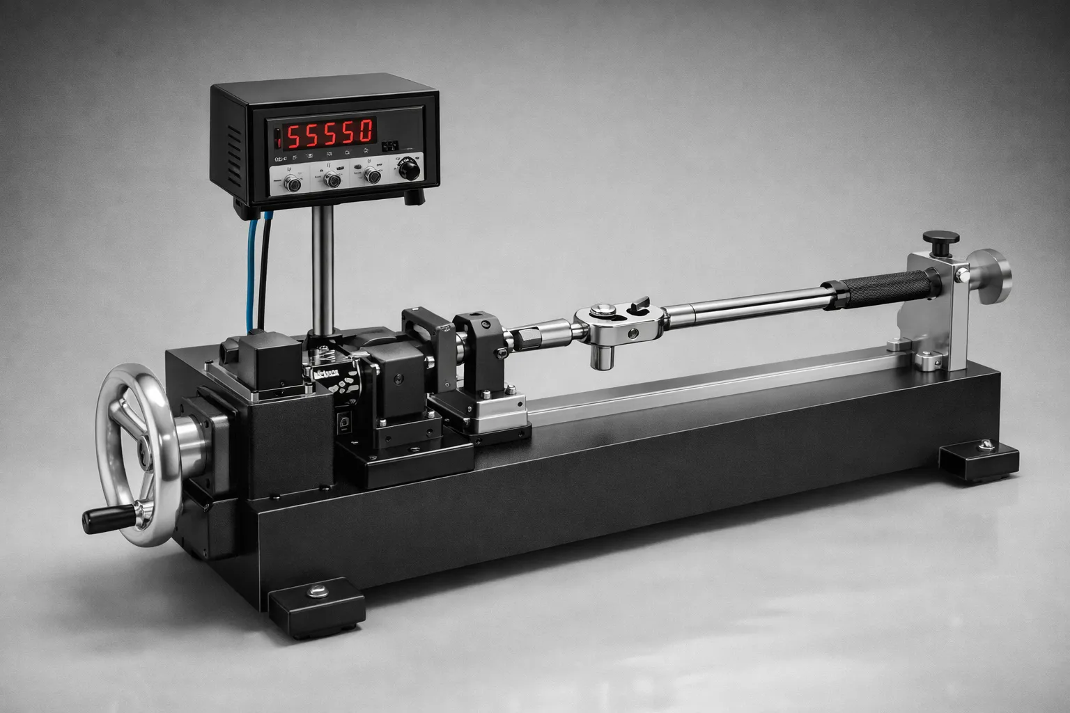
Torque Sensor Calibration Specifics
Torque calibration follows similar principles to force calibration but with important differences:
Reference standard: A certified torque arm with deadweights, or a reference torque sensor calibrated to IS/ISO 6789 or DIN 51309.
Loading: Torque is applied in both clockwise and counter-clockwise directions, and hysteresis is measured in each direction separately.
Alignment: The torque standard and device under test must be coaxially aligned. Angular misalignment introduces bending moments that corrupt the calibration.
Special cases: • Reaction torque sensors are calibrated on a static lever arm with deadweights • Rotary torque sensors require a dynamic calibration rig or can be calibrated statically if they allow shaft locking • Torque wrenches are calibrated per ISO 6789 with specific trigger-point verification
At JRAGRAU, we manufacture dedicated torque wrench calibration systems and verification systems that allow in-house calibration with full traceability.